
Setup Training, Chassis settings for the iRacing FR2.0
Springs, Dampers and ARB

Intro:
The term Vehicle Dynamics describes a field of art, science
and engineering that attempts to describe the behavior of a vehicle while in
motion. Like Aerodynamics, it is a highly complex field of study. There are
thousands of pages written about the subject. The book, Race Car Vehicle
Dynamics by Milliken and Milliken is considered one of the most important
collections of information. Below are a few links for those interested in doing
a lot of reading and thinking,
Fortunately, we don’t need to design the car. We simply need to understand how to make it
go fast! So this article (based on significant
testing) will focus on some very basic core principles that can be applied in
the process of building a setup that will allow our best lap times for the
FR2.0.
Vehicle Dynamics and Chassis Set Up is pretty much all about
making the car go thru corners quickly and that is highly related to how the
weight on the tires changes through the corner.
So, since the car is essentially “held up” with spings, it
is the springs that we will address first.
Formula race cars generally use a “coil over” spring or
springs. The coil spring is located
around or over the damper. (Americans call them shocks—Europeans call them
dampers).The most typical is one coil over assembly (spring and damper) for
each wheel. A typical design (if there is such a thing) is shown below.

The coil over is connected to the wheels thru a quite clever and complex series of rods, and rockers. Most of this complexity is so that the coil overs can be located inside the body, so as to improve aerodynamics. The typical rear set up is often quite similar to the front.
Many iRacing drivers are familiar with the Pro Mazda that
uses this conventional four spring design.
The F2.0 uses a special “monoshock” design for the
front. Instead of two springs, the
entire front is held up with one coil over. There are a few variants of the
monoshock concept, but the principle is simple. The first photo below is a
Dallara IndyCar prototype. The second is one of the early FR2.0.


Photo of FR2.0 Front “Monoshock” and Spring—see link: http://www.motoiq.com/MagazineArticles/ID/4322/PageID/10853/LRS-Formula-at-Magny-Cours.aspx
Europeans familiar with the Mygale Formula BMW will know
that it too used a monoshock to save weight. The Mygale design was different in
that it used a more traditional ARB rather than the sliding crank.
On a conventional design, each wheel is supported by it’s
own spring/damper allowing wheel movement on one side independent of the other.
Under straight line braking for example, both wheels move the same distance,
compressing both of the spring/damper coil over assemblies. When the car rolls
in a turn or strikes a curb, only one wheel moves.
To improve handling, and reduce body roll, the Anti Roll Bar
or ARB is added to the design—essentially connecting the two wheels with a
torsion bar. Now the wheels no longer move independent of each other. When one
wheel goes up relative to the chassis, the torsion bar is twisted and applies
an upward force to the other wheel. (Keep in mind that the wheel generally stays on the ground, so when we
refer to the wheel going up—it really means the chassis is moving down relative
to the ground and the wheel is moving up relative to the chassis. )
Here is a Youtube about ARB’s.
This conventional design is what is used for the rear on the
FR2.0.
But, with the front “monoshock” things are quite
different. Each wheel is connected to
other via the rods connected to the solid “crank”. Under straight line braking
for example, both wheels move the same distance, rotating the “crank” and
compressing the single spring/damper coil over assembly. When the car rolls in
a turn or strikes a curb, since they are connected, when one wheel moves,
instead of the “crank” rotating, the “crank” slides on a shaft and compresses a
spring. The lateral spring, hidden from view in the photo is inside the sliding
mechanism. So, when the car rolls in a
turn, when one wheel moves up, the other moves down with the relative motion
resisted by the hidden spring.
From our point of view, the most important consideration/s
regarding this design are:
A--The roll resistance of the monoshock
assembly in the iRacing FR2.0 is generally much lower than would be the case
for a conventional two coil-over with ARB design. The roll resistance of the front suspension for the iRacing FR2.0 is
also not adjustable. (In real life the internal lateral spring can be changed
and adjusted.) The roll resistance of the front is only slightly affected by
the spring rate on the coil over.
B--There
is no damping forces against chassis roll on the front assembly. All of the damping
forces in chassis roll is accomplished with the rear dampers.
One thing for sure—the design on the FR2.0 works very well
and properly setup, handles as well or better than a car with the more
conventional design.
Just for fun, let’s take a
look at how the suspension interacts. Basically, I increased the Pushrod length
on the right rear from 21.450” to 21.481”. This is an increase of 31 thousanths
of an inch, or 0.8 mm. This would be like having a “weight jacker” like the
IndyCar uses, or would be like adding “wedge” on an oval. Weight is transferred
diagonally. (Starting weights were 278# front and 369# rear)
With the rear ARB disconnected, the RR weight
was increased by 12 pounds. The LF was increased by 121 pounds. The RF and LR
corner weight was decreased by 12 pounds each.
This was good news in that the car behaved pretty much like a typical race car.
This was good news in that the car behaved pretty much like a typical race car.
Now, I connected the rear
ARB, set on a low P1-Stiff setting. Results are shown below. Weight change on
each “corner” was cut in half to 6 pounds, with the ARB doing it’s intended
function, as it was “twisted” to 13.8 ft-lbs.

All this exercise provides is some insight into the function
of the ARB. By adding “Wedge” to the the
RR, the RR is placing a torque on the ARB that pushes down the LR. So the ARB
transferred 6 pounds (50% of the normal cross weight transfer) from one side to
the other on both the front and rear.
I
did the same test with an ARB setting of P4–Stiff which resulted in an ARB
torque of 21.4 ft-lbs. and a transfer of 66% of the normal cross weight
transfer.
When the chassis rolls in a right turn, as opposed to the
weight jack or wedge test, the ARB would be pulled up (relative to the chassis)
making the RR suspension more stiff, and
would reduce the weight on the inside LR and increase the weight on the LF.
This would reduce body roll, make the rear have less grip and the front have
more grip.
Do not underestimate
the effect of the ARB on the iRacing 2.0. Increasing ARB will be most powerful
from Mid Corner to Corner Exit and will dramatically decrease the traction
available on the inside rear tire under acceleration.
Here is a post by my friend, Diederik Kinds who is a Race Engineer on a team that ran the FR2.0:
I worked with this FR2.0 for years. It has an adjustable front ARB system with Bellevilles as depicted in the parts manual, but the pics are not the Tatuus FR2.0 but they look very similar.
There are a lot of Belleville variations for the FARB (preloaded and non-preloaded), none of which are modelled in iRacing.
When the iFR2.0 came out I immediately shot off a mail to iRacing about some setup inconsistencies - 1 about damping settings (bump and rebound were switched) which were subsequently adjusted and the other about lack of FARB adjustment.
I will just copy/paste the answer here:
"In regards to the FARB, essentially the stack system functions like a controlled, and exceedingly stiff, slack rate around center. Because most settings are much too stiff for our numerical integration step we've pegged bar rate to coupled installation stiffness and chassis torsion. This method was the only one, within the iRacing constructs, to allow all available RARB options. The alternative options would have been more restrictive."
On should always keep in mind that settings affect the car the way that iRacing chooses, "within iRacing constructs" as mentioned above ---and their choices may change from time to time. So always test to confirm settings continue to do what you think they do. The iRacing FR2.0 is an iRacing simulation of the real FR2.0.
Spring selection for the FR2.0 is relatively simple. For the
front spring, you can choose 700#, 800# or 900#. For the rears, 800#, 900# or
1000#.
The “correct” choice depends a lot of Driver Preference.
Notice I do not use the term Driver Style.
Our high speed “test track” for aerodynamics was Talladega
Speedway. For testing of the car in corners,
we go to the Centripetal Circuit. (Centripetal force is defined as, “The component of force acting
on a body in curvilinear motion that is directed toward the center of curvature
or axis of rotation,” while centrifugal force is defined as, “The
apparent force, equal and opposite to the centripetal force,
drawing a rotating body away from the center.
So we are testing the Centripetal force produced by the tires of the
car.) I generally go to the lane fourth from the outer one. We run the
test at 123-124 mph at part throttle, burning 0.5 gallons of fuel—then we
measure tire temps to see changes due to changes in spring rates.


Test 1: Running “full” 31/12 downforce, with 700# front spring and
800# rears, with an ARB setting at P1-Stiff.
Result: Front Total 1036; Rear
Total 1048, slight increased wear and temp on RF. Essentially close to balanced
or “neutral” at part throttle. (See
above)
Test 2: Same settings as Test 1 except: 800# front spring and 800#
rear spring. Same result as Test 1
Test 3: Same settings as Test 1 except: 900# front spring and 1000#
rear spring. Same result as Test 1
Conclusion: While
spring rates will dramatically affect handling and “feel” when the car is in
“transition”, slowing down, accelerating, entering the corner or exiting the
corner; spring rate choice will have less effect on the car’s grip and handing
in a “steady state” turn. This may surprise many, including oval track racers
who change springs to effect handling, but keep in mind that even on an oval track,
there is a significant period of time when the car is in “transition”.
A useful learning exercise is
doing this test and noting the way the car responds to throttle. The car will
turn more tightly when the throttle is released and then will want to track out
at full throttle, with no change in steering input. So the car can be steered
with throtlle by changing weight transfer from rear to front and back. Learning
how to control this will make you faster.
The higher spring rates will
result in a faster reaction to the throttle’s steering effect..

Test 4: Same settings as Test 3 except: ARB set at P5-Stiff. With
maximum stiff springs and maximum ARB, the car was quite “twitchy” with very
fast reaction to changes in throttle. Car spun when I released throttle at end
of test. (See above). Result: Front
Total 1041; Rear Total 1064, RR tire wear now same as RF. Note higher LF tire
temps resulting in more weight transferred there by the stiff ARB. Essentially still close to balanced or
“neutral” at part throttle but more tending toward oversteer.
A good video about spring rates:
Now let’s address the Dampers.
The video will define some terms:
Simply put, springs primarily determine the distance the
suspension travels and dampers primarily determine the speed the suspension
travels. Note I said, “primarily”. With a given force, a stiffer spring will be
compressed less, so a stiffer spring does not need to travel as far—hence,
given a certain damper setting, the stiffer spring will absorb a given force
more quickly. In addition, in a “dynamic” scenario, where force is momentary or
short in duration, a stiffer damper can
reduce the distance the suspension travels.
Don’t over-simplify and don’t over-complicate the picture.

Above is the iRacing Setup Screen showing Maximum Compression
(Bump) 0 and Maximum Rebound Stiffness 0.
Following is the iRacing Setup Screen showing Minimum
Compression (Bump) 40 and Minimum Rebound Stiffness -2. There is 40 “clicks” from Maximum to Minimum
Bump. There are 8 “clicks” (0, -.25, -.50 etc to -2.0) from Maximum to Minimum
Rebound.
NOTE: THERE IS A
BIT OF CONFUSION REGARDING THIS, AS “RIGHT” CLICKING DECREASES BUMP AND
INCREASES REBOUND DAMPING. (Some people assumed that right clicking always
increases the setting—this is NOT the case for Bump damping settings. I WILL
ADDRESS THIS WITH SOME TEST RESULTS LATER.

Below is a sample real iRacing Setup Screen (Sample 1) (This one in the hands of an outstanding driver matched the world record at TT conditions.)

Below is another real iRacing Setup Screen (Sample 2) with “softer”
Bump Damping and considerably “softer” Rear Rebound Damping.

It is often a surprise that the typical racing damper has
more damping force in Rebound than in Compression Bump. The reason is that the
spring absorbs most of the compression force applied by bumps and cornering,
while the spring is working against the damper in Rebound. Hence, choosing the correct Rebound setting is
often more critical. 40 clicks for a
smaller force makes each click less in magnitude for Bump compared to 8 clicks
for a much larger damping force.
Here, following are two charts. The first is a graph showing
data from Penske Shock’s dynometer for custom shocks they built according to
specs I provided. The shocks were for a very competitive SCCA Formula Vee I
raced and won with at Summit Point.

The next graph illustrates the dampers on the iRacing 2.0,
for the purpose of understanding the damper settings. I inserted notes on a
graph provided by Penske Shocks for a “typical” double adjustable damper. (The
actual data (force and velocity) is not exactly the same as the FR2.0.

OK, let’s go back to that earlier NOTE: THERE IS A BIT OF CONFUSION REGARDING THIS, AS “RIGHT”
CLICKING DECREASES BUMP AND INCREASES REBOUND DAMPING. (Some people assumed
that right clicking always increases the setting—this is NOT the case for Bump
damping settings. I have tested the
dampers extensively running telemetry at the very bumpy Sebring International
and Lime Rock where the car goes airborne. The test at Sebring was to primarily test if
the dampers could be set at extremes that would “jack up” the car or “clamp
down” the car over a bumpy track. The results indicated that neither was an
issue.
The test at Lime Rock provided an excellent “picture” of the
damping. Below is the first result with Maximum Bump and Rebound Damping.

Next, following is the result with Minimum Damping. In both results, you can clearly see the car “launch”
and go fully airborne with a bit of “twist”.
As the car “lands” first on the left tires, it is clear that the setting
of 40 compression allows much faster and larger suspension travel (same
springs) than the 0 setting. With the lesser damping setting of 40, the damper
is traveling almost twice as fast and the car falls 0.80” inches (20mm) closer to the ground, almost bottoming
out.
One can also see clearly that the car bounces significantly
less with the higher compression and rebound damping. Once the car “bottoms”, the subsequent rise
is significantly more with the lower rebound setting, and “overshoots” by more
than 0.50” above equilibrium.

Well, that’s a lot of info, but let’s summarize as a group of three ABC's.
Springs
A---Stiffer springs reduce suspension travel and chassis
roll, and make the car faster to respond to initial steering input. (Although
this effect is less for changes in the front monoshock.)
B---Stiffer springs makes weight transfer to the front tires
under braking occur faster. (This may require more front brake bias to avoid
rear wheel lockup or conversely may reduce the possibility of front brake
lockup.) And weight transfer to the rear
under acceleration occurs faster. However, most often for maximum drive out of
a slow hairpin, weaker springs on the rear often allow for better acceleration.
C---Stiffer springs often allow the tires to come off the
ground or “unload” on a bumpy track as their static compression is less. If the
track is bumpy, stiffer springs may reduce grip significantly. (Watch the
video.) Stiffer springs reduce the likelihood of the car bottoming when hitting
a bump.
Dampers
A--Stiffer front and rear bump and rebound damping reduce
suspension travel and make the car faster to respond to initial steering input.
(Although this effect is less for changes in the front monoshock.) Reducing
rebound damping can make the inside tires have more grip in a turn.
B--Stiffer front and rear bump and rebound damping makes
weight transfer to the front tires under braking occur faster. (This may
require more front brake bias to avoid rear wheel lockup or conversely may
reduce the possibility of front brake lockup.) The first adjustment is typically to reduce the rear rebound to keep the rear
stable under braking—this will also help to keep the rear tires on the ground
when cresting a hill.
C--Stiffer front rebound and stiffer rear bump damping will
make weight transfer to the rear under acceleration occur faster. (The stiffer
front rebound is sometimes counter-intuitive. And, you may NOT want fast weight
transfer if you are experiencing wheel spin.)
Anti Roll Bar (ARB)
A--The rear ARB will reduce chassis roll. Stiffer settings
reduce more.
B--The rear ARB will take weight from the inside rear tire and transfer much of that to the inside front tire.
C--The rear ARB will dramatically change the “balance” of
the car as there is no adjustment to the front.
Keep the setting the least stiff as possible (Do not disconnect) while
still achieving desired rotation from apex to track out. (We will focus on this
again in the article about the locking differential.)
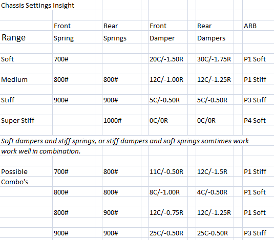
The following chart will provide some insight as to the
ranges for spring choice, damper settings, and ARB settings. You might experiment with the “Possible Combo’s”
settings, changing damper and ARB settings for given spring choices, but they are not intended to be recommended “baseline” settings. You
will need to consider the other important settings for camber, toe, tire
pressure, and differential settings—all to be covered in future articles. All of these settings are related. Your “baseline”
settings for you is what matter. (You will recall, I suggested having three—which would then allow you
to have a starting point for different groups of tracks.) But to create a baseline for you, you will require a bit of experimenting and
testing.
You will recall that I mentioned that chassis settings often have to do with driver preference. I tend to think of drivers fitting into one of two major categories:
The “High Frequency” types that probably relate to driving
racing karts. They prefer the car to be stiff and react to inputs very
quickly. They usually have fast reflexes
and enjoy making numerous and rapid corrections to steering, braking and
throttle inputs as necessary when they exceed the limits.
The “Low Frequency” types that probably relate more to
piloting airplanes. They prefer the car to be less stiff and react to gradual
and deliberate inputs, gradually. They desire the car to navigate the corners
with stable and deliberate inputs to create a smooth arc of travel, with few corrections
being necessary—seeking to always to reach but not exceed the limits.
Both types can be very fast—but the set up needs to “fit”
their preference. To be fast, you must keep the car as close to the limit as
possible at all times. And, remember that a confident driver is a fast driver!
One final note. iRacing has a minimum ride height. The iRacing FR2.0 generally is fastest with the lowest front ride height allowed that will not result in the car bottoming out, hitting curbs when straddling them, etc. Rear ride height is determined by the desired rake and the same restriction of not bottoming out. 0.4 to 0.6 inches static rake is a good place to start. Softer springs tend to result in lower dynamic ride height, but often require a bit more compression bump damping.
You can test ride height with telemetry like Motec or Atlas, but a poor man's quick way is to simply use the iRacing replay camera, adjust the chase view so that your eye is at road level and watch the air gap under the car. iRacing will even display sparks when you bottom out!
A little complicated. Will have to revisit.
ReplyDeleteBut very informative! I've been wondering if I'd ever understand the basics of spings and shocks for a very long time!
Thanks!