The "Latest" Rig

The "Latest" Rig
Bodnar Wheel w HPP Pedals (Added Rift in Summer 2017)

Sunday, December 31, 2017

Setup Training for the iRacing FR2.0-Differential Setup

Differential

Differential—Preload and Ramp Angle


Intro:

When writing about race car dynamics, I often comment that the most mis-understood aspect of setup is front caster settings.  In the FR2.0, the caster is fixed, so it is not an issue.

But, for this car the most mis-understood setting is probably the Differential.

Race cars generally use one of four basic types of differentials:

1--Open
2—Spool or Locked
3--Limited Slip
4--Locker

The Open differential was developed to allow the tires on each side R-L to turn different speeds—helpful when turning. Torque is applied equally to both tires, with the torque applied being determined by the tire with the LEAST traction.

The Spool differential is essentially where the tires on each side are locked and always turn at the same speed. Same torque applied to both tires.

The Limited Slip differential is an Open differential with a mechanism that allows to act like a Spool differential, up to a limit, afterwhich the tires on each side R-L may turn at different speeds.

The Locker is a special device that acts like an Open differential when “coasting” or decelerating and a Spool when accelerating. (e.g. Detroit Locker)

The FR2.0 uses a Limited Slip Differential.

The following Youtube video’s are quite informative.


The above drawings illustrates the Ramp Angles very well.  Often it is confusing that a lower Ramp Angle produces more locking and a higher Ramp Angle produces less locking, but from the video and the drawings, you will see that the lower angle is essentially a “sharper” wedge that produces more sideward force against the clutches.

The Diff Preload is created by springs that push against the clutches all the time.

The Ramp Angle creates additional force against the clutches during “coast” and “acceleration”.

The more force applied to the clutches, the more locking force===the more the differential acts like a Spool.

The less force applied to the clutches the less locking force==the more the differential acts like an Open Differential.

The following link will take you to an excellent writeup by a group of Sim Racers in Denmark where I found the drawing.

 http://www.intothered.dk/simracing/differential.html

Another link that you will find useful was written by my friend, Craig Taylor at Taylor Race Engineering in Plano, Texas.  Craig and I raced against each other in SCCA FF1600 during the 1980’s. at Texas World Speedway. He was really fast and like me, was an airplane pilot. He later went on to win the US F2000 Championship.


Oversteer (Loose) and Understeer (Push)

Determining exactly how the car will react to changes in the differential is much more complex than most people realize. So much is “going on” with the suspension, brakes and steering, that the answer as to specific cause and effect of changes in diff settings is: IT DEPENDS!

For those interested, read the paper of research at GM over many years authored by Bundorf, who actually created a form of analysis for studying dynamic understeer/oversteer.  Bundorf Analysis where understeer is measured in units of degrees of additional yaw per g of lateral acceleration.

Following is the link.
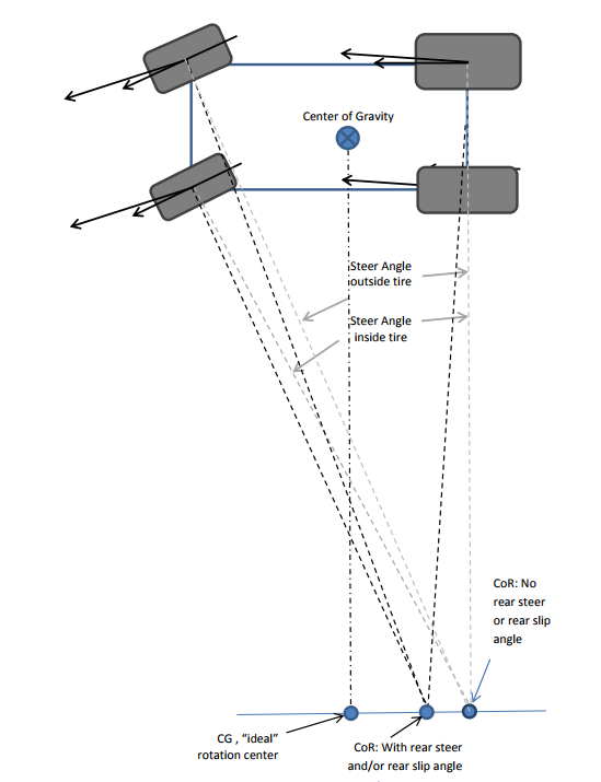


The above illustration shows what the driver is sensing is changes in relative slip angles on the front steering tires vs the rear powered tires.  Here is the link to the entire article:

https://sweetmfg.biz/uploads/files/tech-04understandingsteering-4.pdf


Practical

OK, lots of theory and engineering stuff.  Let’s again do some real world testing and practical info of how to make the IRacing FR2.0 go fast.

Here are the screens for setting the Diff Preload and Diff Ramp angles. What many  don’t realize is iRacing provides a HUGE range of adjustment in Diff Preload from a low of -100 ft-lbs to a high of  +100 ft-lbs. That is a total range of 200 ft-lbs—theoretically in the amount of torque that it would take to rotate one wheel while the other is stationary. (I assume -100 is zero and +100 is 200 ft-lbs total but I have no way of knowing that for sure. The most common settings I have seen for Diff Preload is in the 0-25 range.)

For the Diff Ramp Angle, there are only two choices: “70 coast/65 drive” and “65 coast/70 drive”.

The 65 is the angle of “wedge” mentioned earlier and provides more locking force.  So, generally, unless you love driving karts with Spool-like solid axles where you throw or wrestle the car into the corners, generally “70 coast/65 drive” will produce the best handling car as it will have less locking and understeer during Corner Entry and Mid Corner. (Mid Corner understeer is generally not fast.)


Minimum Locking= -100


Maximum Locking = +100


“Typical” Locking =  +10

To determine the effect of changes, I tested the car at all three of these setting examples at several tracks. Actual engineering data was hard to collect, so here is some “anecdotal” evidence.  Try it for yourself. 

In T1 at Silverstone, with Minimum Locking, I got a lot of trailing throttle oversteer on corner entry—the car felt a lot like a Pro Mazda with an Open Diff. My steering input was quite low at the apex. The feeling of oversteer disappeared as I tracked out and the car felt a bit “understeery” on Corner Exit.

In the last hairpin at Sonoma, the car with Maximum Locking seemed to have a great deal of understeer on Corner Entry and then felt a bit “oversteery” on exit.

Hmmm—Minimum Locking a bit like an Open Diff—like the Pro Mazda. Maximum Locking a bit like a Spool---like a front engine GT3.

Keep in mind this was testing at the extreme settings.

I really wanted data, not “feelings”, so I tried the car at Milwaukee.  A flat oval with big radius corners. Then at Martinsville—a flat oval with relatively sharp corners.  Ahh! Eureka!!
See the iSpeed Telemetry snapshot:


Here is a link to the replay of the test at Martinsville in the FR2.0


More steering input on Corner Entry and Mid Corner (A-B) would indicate understeer.  Less steering input on Corner Exit (B-C) would indicate oversteer or almost neutral. This is what I found.

The more locking force (mostly from Diff Preload setting) the more the car pushed or understeered in Corner Entry and Mid Corner. Lots more, like 20+ degrees more steering angle required to maintain the same arc. Because of the additional steering input at Mid Corner with more locking force, the car has a bit more rotating momentum or inertia as it accelerates and hence needs less steering on exit.


Keep in mind that even with -100 Diff Preload, because of the 70 coast Ramp Angle, there is still quite a bit of locking force on coast. 

Discussion

A Spool Diff works OK on a dirt oval. I have driven one in a Pro Dirt Legends Series in Central PA. It can be made to work on a paved oval. But, it does not work very well on a road course. Why?

A Spool resists the turning forces on a car and causes understeer, UNLESS, you can adjust the tire size or “stagger” so that the inside and outside tires rotate at different speeds, and unless you can adjust what is called the “bite” and “crossweight” as the car "rolls thru" Mid Corner and accelerates to Corner Exit. So on ovals, you can setup the car to turn left better than it turns right. (An Asymetrical Setup for ovals.)

An Open Diff does not resist the turning forces on a car. Most cars with an Open Diff have some trailing throttle oversteer—not because of the differential, but because of all the other setup parameters. The Open Diff simply does not offset any of the ovesteering tendencies. (Although it does seem to have a bit of oversteer induced immediately as you lift the throttle and the diff sees engine braking resistance.)

Because an Open Diff will stop delivering torque when the inside wheel loses traction, it often tends to accelerate less powerfully off the corner. And, when trail braking, it is easy to lock up the inside tire, which often produces snap oversteer. 

A Limited Slip differential is a hybrid, that acts a bit like an Open Diff and a bit like a Spool. The Limited Slip Diff will introduce understeer during corner entry, offsetting some or all of the trailing throttle oversteer tendencies. A Limited Slip differential will allow much more trail braking than would be possible with an Open Diff.

A  Limited Slip differential does not have as much corner exit understeer as would be evident with a Spool, and because at the limit, it allows the tires to turn at different speeds, while still transmitting torque, it will allow for significantly more corner exit acceleration.

As one realizes from driving IndyCar or F1, even a Limited Slip differential will allow the car to be loose when applying power if traction is lost or even limited by the inside tire because of springs or ARB settings that are too stiff.

Also, as oval track drivers know, there is a phenomenon known as Tight In/Loose Out caused by driver input overcompensating for understeer at Mid Corner. Here the driver enters more steering input at Mid Corner to make the car rotate, and then the car becomes loose or oversteery on corner exit. 

Finally, the sharper the corner—the lesser the corner radius, the less locking you will want.  The larger the corner radius, the more locking you will want.

My advice

Set the Ramp Angle at “70 coast/65 drive” and forget it unless you really love a lot of understeer on Corner Entry. Use the Diff Preload for “fine tuning”.

Initially set up the Diff Preload somewhere in the -10 to +25 range depending on your preference for understeer during Corner Entry and the amount of trail braking you prefer.  The higher the more understeer you will get, but the the more trail braking you can use to get the car to rotate. This intial setting will be your “neutral” or “baseline”. Experiment to determine your “preference” in this range.

Then, AFTER you think you have everything else (Downforce, Springs, Dampers, ARB’s, Camber, Tire Pressure, Toe) just the way you want it, go back and experiment to see if any changes improve your lap times.

One final note. Keep in mind that iRacing provided the huge 200 ft-lb range in Diff preload for a reason. They seldom provide a range that is completely irrelevant, so do not be afraid to experiment with settings that you might not often see or have seen in the “shared “ settings.  I found the car surprisingly drivable on many tracks with both extreme settings—I achieved identical lap times at Milwaukee, Silverstone and Sonoma—by just adjusting my driving to the car’s limits. When I set the preload at +100, I expected the car to "push like a snow plow" but it did not.  On tracks with sharp corners, like Martinsville, the low Diff settings allowed for significantly faster laps.

BTW--the little 210hp FR2.0 just about matched the XFinity car times at Martinsville!


NOTE:  You will find that many drivers will run a much "stiffer" rear--with 900# springs and quite a bit of ARB. This makes the car quite "loose" or oversteery----so they offset this by increasing Diff Preload to 40+ and change ramp setting to 65coast/70 drive. These same drivers tend to run much less front brake bias.

My personal view is much of this driver preference has to do with how they trail brake. Normally, higher Diff Preload can be run with a heavy trail braking technique, but lower front brake bias makes trail braking more difficult. So this "stiffer" set up preference is generally a desire to rotate the car during corner entry without trail braking.


Thursday, December 28, 2017

Setup Training, Chassis settings for the iRacing FR2.0

Setup Training, Chassis settings for the iRacing FR2.0

Springs, Dampers and ARB

Intro:

The term Vehicle Dynamics describes a field of art, science and engineering that attempts to describe the behavior of a vehicle while in motion. Like Aerodynamics, it is a highly complex field of study. There are thousands of pages written about the subject. The book, Race Car Vehicle Dynamics by Milliken and Milliken is considered one of the most important collections of information. Below are a few links for those interested in doing a lot of reading and thinking,


Fortunately, we don’t need to design the car.  We simply need to understand how to make it go fast!  So this article (based on significant testing) will focus on some very basic core principles that can be applied in the process of building a setup that will allow our best lap times for the FR2.0.

Vehicle Dynamics and Chassis Set Up is pretty much all about making the car go thru corners quickly and that is highly related to how the weight on the tires changes through the corner.

So, since the car is essentially “held up” with spings, it is the springs that we will address first.

Formula race cars generally use a “coil over” spring or springs.  The coil spring is located around or over the damper. (Americans call them shocks—Europeans call them dampers).The most typical is one coil over assembly (spring and damper) for each wheel. A typical design (if there is such a thing) is shown below.


The coil over is connected to the wheels thru a quite clever and complex series of rods, and rockers.  Most of this complexity is so that the coil overs can be located inside the body, so as to improve aerodynamics. The typical rear set up is often quite similar to the front.

Many iRacing drivers are familiar with the Pro Mazda that uses this conventional four spring design.

The F2.0 uses a special “monoshock” design for the front.  Instead of two springs, the entire front is held up with one coil over. There are a few variants of the monoshock concept, but the principle is simple. The first photo below is a Dallara IndyCar prototype. The second is one of the early FR2.0.


Photo of FR2.0 Front “Monoshock” and Spring—see link: http://www.motoiq.com/MagazineArticles/ID/4322/PageID/10853/LRS-Formula-at-Magny-Cours.aspx

Europeans familiar with the Mygale Formula BMW will know that it too used a monoshock to save weight. The Mygale design was different in that it used a more traditional ARB rather than the sliding crank.

On a conventional design, each wheel is supported by it’s own spring/damper allowing wheel movement on one side independent of the other. Under straight line braking for example, both wheels move the same distance, compressing both of the spring/damper coil over assemblies. When the car rolls in a turn or strikes a curb, only one wheel moves.

To improve handling, and reduce body roll, the Anti Roll Bar or ARB is added to the design—essentially connecting the two wheels with a torsion bar. Now the wheels no longer move independent of each other. When one wheel goes up relative to the chassis, the torsion bar is twisted and applies an upward force to the other wheel. (Keep in mind that the wheel  generally stays on the ground, so when we refer to the wheel going up—it really means the chassis is moving down relative to the ground and the wheel is moving up relative to the chassis. )

Here is a Youtube about ARB’s.

This conventional design is what is used for the rear on the FR2.0.

But, with the front “monoshock” things are quite different.  Each wheel is connected to other via the rods connected to the solid “crank”. Under straight line braking for example, both wheels move the same distance, rotating the “crank” and compressing the single spring/damper coil over assembly. When the car rolls in a turn or strikes a curb, since they are connected, when one wheel moves, instead of the “crank” rotating, the “crank” slides on a shaft and compresses a spring. The lateral spring, hidden from view in the photo is inside the sliding mechanism.  So, when the car rolls in a turn, when one wheel moves up, the other moves down with the relative motion resisted by the hidden spring.

From our point of view, the most important consideration/s regarding this design are:

A--The roll resistance of the monoshock assembly in the iRacing FR2.0 is generally much lower than would be the case for a conventional two coil-over with ARB design. The roll resistance of the front suspension for the iRacing FR2.0 is also not adjustable. (In real life the internal lateral spring can be changed and adjusted.) The roll resistance of the front is only slightly affected by the spring rate on the coil over.

B--There is no damping forces against chassis roll on the front assembly. All of the damping forces in chassis roll is accomplished with the rear dampers.

One thing for sure—the design on the FR2.0 works very well and properly setup, handles as well or better than a car with the more conventional design.

Just for fun, let’s take a look at how the suspension interacts. Basically, I increased the Pushrod length on the right rear from 21.450” to 21.481”. This is an increase of 31 thousanths of an inch, or 0.8 mm. This would be like having a “weight jacker” like the IndyCar uses, or would be like adding “wedge” on an oval. Weight is transferred diagonally. (Starting weights were 278# front and 369# rear)

With the rear ARB disconnected, the RR weight was increased by 12 pounds. The LF was increased by 121 pounds. The RF and LR corner weight was decreased by 12 pounds each.  

This was good news in that the car behaved pretty much like a typical race car.

Now, I connected the rear ARB, set on a low P1-Stiff setting. Results are shown below. Weight change on each “corner” was cut in half to 6 pounds, with the ARB doing it’s intended function, as it was “twisted” to 13.8 ft-lbs.


All this exercise provides is some insight into the function of the ARB.  By adding “Wedge” to the the RR, the RR is placing a torque on the ARB that pushes down the LR. So the ARB transferred 6 pounds (50% of the normal cross weight transfer) from one side to the other on both the front and rear.  

I did the same test with an ARB setting of P4–Stiff which resulted in an ARB torque of 21.4 ft-lbs. and a transfer of 66% of the normal cross weight transfer. 

When the chassis rolls in a right turn, as opposed to the weight jack or wedge test, the ARB would be pulled up (relative to the chassis) making the RR suspension more stiff,  and would reduce the weight on the inside LR and increase the weight on the LF. This would reduce body roll, make the rear have less grip and the front have more grip.

Do not underestimate the effect of the ARB on the iRacing 2.0. Increasing ARB will be most powerful from Mid Corner to Corner Exit and will dramatically decrease the traction available on the inside rear tire under acceleration.

Here is a post by my friend, Diederik Kinds who is a Race Engineer on a team that ran the FR2.0: 

I worked with this FR2.0 for years. It has an adjustable front ARB system with Bellevilles as depicted in the parts manual, but the pics are not the Tatuus FR2.0 but they look very similar.

There are a lot of Belleville variations for the FARB (preloaded and non-preloaded), none of which are modelled in iRacing.

When the iFR2.0 came out I immediately shot off a mail to iRacing about some setup inconsistencies - 1 about damping settings (bump and rebound were switched) which were subsequently adjusted and the other about lack of FARB adjustment.

I will just copy/paste the answer here:
"In regards to the FARB, essentially the stack system functions like a controlled, and exceedingly stiff, slack rate around center. Because most settings are much too stiff for our numerical integration step we've pegged bar rate to coupled installation stiffness and chassis torsion. This method was the only one, within the iRacing constructs, to allow all available RARB options. The alternative options would have been more restrictive."


On should always keep in mind that settings affect the car the way that iRacing chooses, "within iRacing constructs" as mentioned above ---and their choices may change from time to time. So always test to confirm settings continue to do what you think they do. The iRacing FR2.0 is an iRacing simulation of the real FR2.0. 


Spring selection for the FR2.0 is relatively simple. For the front spring, you can choose 700#, 800# or 900#. For the rears, 800#, 900# or 1000#.

The “correct” choice depends a lot of Driver Preference. Notice I do not use the term Driver Style. 

Our high speed “test track” for aerodynamics was Talladega Speedway. For testing of the car in corners,  we go to the Centripetal Circuit. (Centripetal force is defined as, “The component of force acting on a body in curvilinear motion that is directed toward the center of curvature or axis of rotation,” while centrifugal force is defined as, “The apparent force, equal and opposite to the centripetal force, drawing a rotating body away from the center.  So we are testing the Centripetal force produced by the tires of the car.)  I generally go to the lane fourth from the outer one. We run the test at 123-124 mph at part throttle, burning 0.5 gallons of fuel—then we measure tire temps to see changes due to changes in spring rates.


Test 1: Running “full” 31/12 downforce, with 700# front spring and 800# rears, with an ARB setting at P1-Stiff.  Result:  Front Total 1036; Rear Total 1048, slight increased wear and temp on RF. Essentially close to balanced or “neutral” at part throttle.  (See above)

Test 2: Same settings as Test 1 except: 800# front spring and 800# rear spring. Same result as Test 1

Test 3: Same settings as Test 1 except: 900# front spring and 1000# rear spring. Same result as Test 1

Conclusion: While spring rates will dramatically affect handling and “feel” when the car is in “transition”, slowing down, accelerating, entering the corner or exiting the corner; spring rate choice will have less effect on the car’s grip and handing in a “steady state” turn. This may surprise many, including oval track racers who change springs to effect handling,  but keep in mind that even on an oval track, there is a significant period of time when the car is in “transition”.

A useful learning exercise is doing this test and noting the way the car responds to throttle. The car will turn more tightly when the throttle is released and then will want to track out at full throttle, with no change in steering input. So the car can be steered with throtlle by changing weight transfer from rear to front and back. Learning how to control this will make you faster.

The higher spring rates will result in a faster reaction to the throttle’s steering effect..


Test 4:  Same settings as Test 3 except: ARB set at P5-Stiff. With maximum stiff springs and maximum ARB, the car was quite “twitchy” with very fast reaction to changes in throttle. Car spun when I released throttle at end of test. (See above). Result:  Front Total 1041; Rear Total 1064, RR tire wear now same as RF. Note higher LF tire temps resulting in more weight transferred there by the stiff ARB.  Essentially still close to balanced or “neutral” at part throttle but more tending toward oversteer. 

A good video about spring rates:


Now let’s address the Dampers.

The video will define some terms:


Simply put, springs primarily determine the distance the suspension travels and dampers primarily determine the speed the suspension travels.  Note I said, “primarily”.  With a given force, a stiffer spring will be compressed less, so a stiffer spring does not need to travel as far—hence, given a certain damper setting, the stiffer spring will absorb a given force more quickly. In addition, in a “dynamic” scenario, where force is momentary or short in duration, a stiffer  damper can reduce the distance the suspension travels.

Don’t over-simplify and don’t over-complicate the picture.


Above is the iRacing Setup Screen showing Maximum Compression (Bump) 0 and Maximum Rebound Stiffness 0.

Following is the iRacing Setup Screen showing Minimum Compression (Bump) 40 and Minimum Rebound Stiffness -2.  There is 40 “clicks” from Maximum to Minimum Bump. There are 8 “clicks” (0, -.25, -.50 etc to -2.0) from Maximum to Minimum Rebound.

NOTE: THERE IS A BIT OF CONFUSION REGARDING THIS, AS “RIGHT” CLICKING DECREASES BUMP AND INCREASES REBOUND DAMPING. (Some people assumed that right clicking always increases the setting—this is NOT the case for Bump damping settings. I WILL ADDRESS THIS WITH SOME TEST RESULTS LATER.


Below is a sample real iRacing Setup Screen (Sample 1) (This one in the hands of an outstanding driver matched the world record at TT conditions.)


Below is another real iRacing Setup Screen (Sample 2) with “softer” Bump Damping and considerably “softer” Rear Rebound Damping.


It is often a surprise that the typical racing damper has more damping force in Rebound than in Compression Bump. The reason is that the spring absorbs most of the compression force applied by bumps and cornering, while the spring is working against the damper in Rebound.  Hence, choosing the correct Rebound setting is often more critical.  40 clicks for a smaller force makes each click less in magnitude for Bump compared to 8 clicks for a much larger damping force.

Here, following are two charts. The first is a graph showing data from Penske Shock’s dynometer for custom shocks they built according to specs I provided. The shocks were for a very competitive SCCA Formula Vee I raced and won with at Summit Point. 


The next graph illustrates the dampers on the iRacing 2.0, for the purpose of understanding the damper settings. I inserted notes on a graph provided by Penske Shocks for a “typical” double adjustable damper. (The actual data (force and velocity) is not exactly the same as the FR2.0.


OK, let’s go back to that earlier NOTE: THERE IS A BIT OF CONFUSION REGARDING THIS, AS “RIGHT” CLICKING DECREASES BUMP AND INCREASES REBOUND DAMPING. (Some people assumed that right clicking always increases the setting—this is NOT the case for Bump damping settings.  I have tested the dampers extensively running telemetry at the very bumpy Sebring International and Lime Rock where the car goes airborne.  The test at Sebring was to primarily test if the dampers could be set at extremes that would “jack up” the car or “clamp down” the car over a bumpy track. The results indicated that neither was an issue.

The test at Lime Rock provided an excellent “picture” of the damping. Below is the first result with Maximum Bump and Rebound Damping.


Next, following is the result with Minimum Damping.  In both results, you can clearly see the car “launch” and go fully airborne with a bit of “twist”.  As the car “lands” first on the left tires, it is clear that the setting of 40 compression allows much faster and larger suspension travel (same springs) than the 0 setting. With the lesser damping setting of 40, the damper is traveling almost twice as fast and the car falls 0.80” inches  (20mm) closer to the ground, almost bottoming out.

One can also see clearly that the car bounces significantly less with the higher compression and rebound damping.  Once the car “bottoms”, the subsequent rise is significantly more with the lower rebound setting, and “overshoots” by more than 0.50” above equilibrium.


Well, that’s a lot of info, but let’s summarize as a group of three ABC's.

Springs

A---Stiffer springs reduce suspension travel and chassis roll, and make the car faster to respond to initial steering input. (Although this effect is less for changes in the front monoshock.)

B---Stiffer springs makes weight transfer to the front tires under braking occur faster. (This may require more front brake bias to avoid rear wheel lockup or conversely may reduce the possibility of front brake lockup.)  And weight transfer to the rear under acceleration occurs faster. However, most often for maximum drive out of a slow hairpin, weaker springs on the rear often allow for better acceleration.

C---Stiffer springs often allow the tires to come off the ground or “unload” on a bumpy track as their static compression is less. If the track is bumpy, stiffer springs may reduce grip significantly. (Watch the video.) Stiffer springs reduce the likelihood of the car bottoming when hitting a bump.

  
Dampers

A--Stiffer front and rear bump and rebound damping reduce suspension travel and make the car faster to respond to initial steering input. (Although this effect is less for changes in the front monoshock.) Reducing rebound damping can make the inside tires have more grip in a turn.

B--Stiffer front and rear bump and rebound damping makes weight transfer to the front tires under braking occur faster. (This may require more front brake bias to avoid rear wheel lockup or conversely may reduce the possibility of front brake lockup.)  The first adjustment is typically to  reduce the rear rebound to keep the rear stable under braking—this will also help to keep the rear tires on the ground when cresting a hill.

C--Stiffer front rebound and stiffer rear bump damping will make weight transfer to the rear under acceleration occur faster. (The stiffer front rebound is sometimes counter-intuitive. And, you may NOT want fast weight transfer if you are experiencing wheel spin.)

Anti Roll Bar (ARB)

A--The rear ARB will reduce chassis roll. Stiffer settings reduce more.

B--The rear ARB will take weight from the inside rear tire and transfer much of that to the inside front tire.

C--The rear ARB will dramatically change the “balance” of the car as there is no adjustment to the front.  Keep the setting the least stiff as possible (Do not disconnect) while still achieving desired rotation from apex to track out. (We will focus on this again in the article about the locking differential.)

The following chart will provide some insight as to the ranges for spring choice, damper settings, and ARB settings.  You might experiment with the “Possible Combo’s” settings, changing damper and ARB settings for given spring choices, but they are not intended to be recommended “baseline” settings. You will need to consider the other important settings for camber, toe, tire pressure, and differential settings—all to be covered in future articles. All of these settings are related.  Your “baseline” settings for you is what matter. (You will recall, I suggested having three—which would then allow you to have a starting point for different groups of tracks.)  But to create a baseline for you,  you will require a bit of experimenting and testing.


You will recall that I mentioned that chassis settings often have to do with driver preference.  I tend to think of drivers fitting into one of two major categories:

The “High Frequency” types that probably relate to driving racing karts. They prefer the car to be stiff and react to inputs very quickly.  They usually have fast reflexes and enjoy making numerous and rapid corrections to steering, braking and throttle inputs as necessary when they exceed the limits.

The “Low Frequency” types that probably relate more to piloting airplanes. They prefer the car to be less stiff and react to gradual and deliberate inputs, gradually. They desire the car to navigate the corners with stable and deliberate inputs to create a smooth arc of travel, with few corrections being necessary—seeking to always to reach but not exceed the limits.

Both types can be very fast—but the set up needs to “fit” their preference. To be fast, you must keep the car as close to the limit as possible at all times. And, remember that a confident driver is a fast driver!

One final note. iRacing has a minimum ride height. The iRacing FR2.0 generally is fastest with the lowest front ride height allowed that will not result in the car bottoming out, hitting curbs when straddling them, etc. Rear ride height is determined by the desired rake and the same restriction of not bottoming out. 0.4 to 0.6 inches static rake is a good place to start.   

Softer springs tend to result in lower dynamic ride height, but often require a bit more compression bump damping.

You can test ride height with telemetry like Motec or Atlas, but a poor man's quick way is to simply use the iRacing replay camera, adjust the chase view so that your eye is at road level and watch the air gap under the car. iRacing will even display sparks when you bottom out!